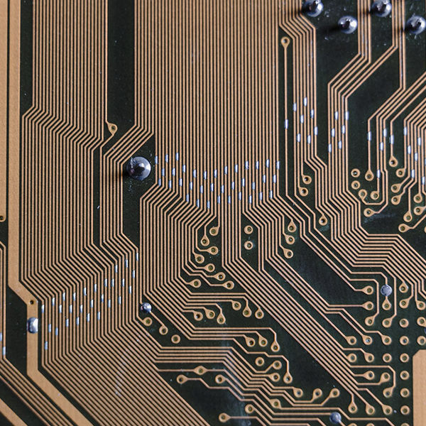
Printed Circuit Boards (PCBs) are the unsung heroes of modern electronics, serving as the foundation for nearly every device we use. But have you ever wondered how these intricate green boards are made? The journey from a digital design file to a physical, functional circuit board is a precise and fascinating process involving multiple, highly-controlled stages. As a leading PCB manufacturer with extensive experience, Tri-Win Circuits is here to pull back the curtain on the complete PCB fabrication process.
Tri-Win will walk you through each critical step, from initial design review to final quality inspection. Understanding this process not only demystifies how your electronics work but also highlights why choosing an experienced manufacturing partner is crucial for the success of your project.
In This Article:
How Does the Journey from a Digital Design to a Physical Board Begin?
Before any physical manufacturing can occur, the process begins in the digital realm. This foundational stage is all about ensuring the design is flawless and perfectly optimized for manufacturing. A mistake here can lead to costly delays and dysfunctional boards.
The Blueprint: Gerber Files
The standard industry blueprint for PCB fabrication is the Gerber file. This file format acts as a universal language between you (the designer) and us (the manufacturer). It contains all the essential information needed to build the board, including the copper layers, solder mask, silkscreen, drill data, and board outline. A complete and accurate set of Gerber files is the non-negotiable starting point for any project.
Engineering Review and DFM Check
This is where an expert partner like Tri-Win Circuits adds immediate value. Once we receive your Gerber files, our experienced engineers don’t just start building; they conduct a thorough Design for Manufacturability (DFM) check. This critical review process identifies any potential issues that could hinder the manufacturing process or compromise the final board’s integrity. We look for things like:
- Trace Spacing and Width: Are the copper traces too close together or too thin for reliable performance?
- Drill Hole Clearances: Is there enough space between drill holes and other board features to prevent short circuits?
- Missing Information: Are all necessary files, like the drill file or board outline, present and correct?
- Physical Constraints: Does the design meet the physical limitations of our advanced manufacturing equipment?
By catching these issues early, our DFM service saves you time, money, and the frustration of receiving a batch of unusable PCBs. It’s a cornerstone of our commitment to quality and partnership.
What Are the Core Materials in a Printed Circuit Board?
The base material of a PCB, known as the substrate, determines its physical and electrical properties. The most common material is FR-4, but different applications demand different materials. At Tri-Win Circuits, we work with a wide array to meet the diverse needs of our global clients, from simple prototypes to high-frequency communication devices.
| Material Type | Key Characteristics | Common Applications |
|---|---|---|
| FR-4 (Flame Retardant 4) | Glass-reinforced epoxy laminate. Cost-effective, strong, and has good electrical insulation. The industry workhorse. | Consumer electronics, computer hardware, industrial controls. |
| Flexible (Polyimide) | Can be bent and flexed without breaking the circuit. Lightweight and durable. | Wearable technology, medical devices, automotive electronics, cameras. |
| Metal Core (e.g., Aluminum) | Excellent thermal conductivity, designed to dissipate heat away from components. | LED lighting systems, power supplies, automotive headlights. |
| High-Frequency (Rogers, Teflon) | Maintains a stable dielectric constant at high frequencies, ensuring signal integrity. | RF/Microwave systems, communication antennas, high-speed digital circuits. |
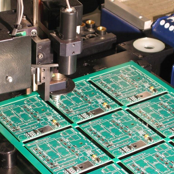
What Are the Key Steps in the PCB Fabrication Process?
With the design confirmed and materials selected, the physical creation of the circuit board begins. This is a multi-step process that transforms a simple laminate sheet into a complex electronic foundation.
Step 1: Printing Inner Layers & Etching
For multi-layer PCBs, the process starts with the inner layers. We take a core laminate sheet pre-bonded with copper foil on both sides. The circuit pattern from your Gerber file is printed onto this core using a light-sensitive film called a “photoresist.” The board is then exposed to UV light, which hardens the photoresist over the areas that will become the copper traces. The board is then submerged in a chemical solution that etches away, or removes, the unprotected copper, leaving only the desired circuit pattern behind.
Step 2: Lamination
This step is where a multi-layer board gets its structure. The etched inner-layer cores are stacked together with layers of “prepreg”—a fiberglass cloth pre-impregnated with epoxy resin. The stack-up (e.g., copper foil, prepreg, inner core, prepreg, copper foil) is then placed into a lamination press. Under immense pressure and high temperature, the prepreg resin melts and fuses all the layers together into a single, solid multi-layer board.
Step 3: Drilling
Holes, known as “vias,” must be drilled through the board to connect the different layers or to allow for component leads. This is a highly precise process performed by computer-controlled drill machines that can create thousands of holes with microscopic accuracy. The location and size of every hole are dictated by your drill file.
Step 4: Copper Plating (Electroless & Electrolytic)
After drilling, the inside walls of the holes are non-conductive. To make them conductive, a very thin layer of copper is deposited over the entire board surface, including inside the newly drilled holes, through an electroless copper plating process. This is followed by a thicker layer of copper applied through electrolytic plating (electroplating), building up the copper thickness on the surface layers and through the holes (vias) to create robust electrical connections between layers.
Step 5: Outer Layer Imaging & Etching
This process is similar to Step 1 but is performed on the outer layers of the board. A photoresist is applied, and the outer layer circuit pattern is imaged. This time, the photoresist protects the areas that will *not* be part of the circuit. The board is then plated with tin, which protects the desired copper circuitry. The photoresist is stripped, and the board is etched again, removing the unwanted bare copper and leaving only the tin-protected traces and pads.
Step 6: Applying the Solder Mask
The iconic “green” of most PCBs comes from the solder mask. This epoxy-based layer is applied over the entire board surface. Its primary purposes are to protect the copper traces from oxidation and to prevent solder bridges from forming between closely spaced pads during the assembly process. The solder mask is exposed to UV light through a film, hardening it everywhere except on the pads where components will be soldered.
Step 7: Silkscreen & Surface Finish
Next, the silkscreen layer is printed onto the board. This layer contains reference designators, component outlines, logos, and other markings that aid in assembly and troubleshooting. Finally, a surface finish is applied to the exposed copper pads. This finish (e.g., HASL, ENIG, OSP) protects the pads from oxidation and provides a solderable surface for component assembly. The choice of finish depends on the application, component type, and cost requirements.
How Is Quality Ensured After Fabrication?
A fabricated board is useless if it doesn’t work. Rigorous testing is the final and most critical phase before a PCB is shipped.
Electrical Testing (E-Test)
Every single multi-layer board we produce at Tri-Win Circuits undergoes a 100% electrical test. Using specialized fixtures like a flying probe or bed-of-nails tester, we check for two things: continuity (ensuring all intended connections are complete) and isolation (ensuring there are no short circuits between unconnected nets). This automated test compares the finished board against your original Gerber data to guarantee it is electrically perfect.
Final Visual Inspection
Our quality control team performs a final, thorough visual inspection to check for any cosmetic defects, ensure the board dimensions are correct, and verify that all specifications from your order have been met. Only after passing this meticulous inspection, backed by our UL and ISO9001 certifications, is the board vacuum-sealed and prepared for shipment.
Why Is Your Manufacturing Partner So Important?
As you can see, PCB fabrication is a complex, precision-driven process. The quality of your final product is directly dependent on the expertise, technology, and quality control of your manufacturing partner. At Tri-Win Circuits, we offer more than just fabrication; we provide a complete, one-stop solution.
From our free DFM check and 24/7 technical support to our extensive capabilities in Rigid, Flex, Rigid-Flex, and Metal Core PCBs, we are equipped to handle your project with the excellence it deserves. Whether you need a small batch of quick-turn prototypes or a large-scale production run, our commitment to quality and customer service ensures your vision becomes a reality. We even offer seamless PCB Assembly (PCBA) services to take your board from fabrication to fully functional.
Ready to start your next PCB project? Contact Tri-Win Circuits today for a quote and experience the difference that a true manufacturing partner can make.