In the intricate world of electronics, Printed Circuit Boards (PCBs) are the foundation upon which all components operate. While microchips and capacitors often steal the spotlight, the unsung heroes of any PCB are the traces. These slender copper pathways are the board’s nervous system, carrying critical signals and power between components. The quality of your product—its performance, reliability, and longevity—is directly tied to the precision of its trace pcb fabrication. This guide will illuminate the journey of a PCB trace, from a line in a digital file to a physical, high-performance conductor.

Article Outline
- What Exactly Constitutes a PCB Trace?
- Why is Flawless Trace Design So Crucial for Your Device’s Performance?
- Which Key Factors Dictate Your PCB Trace Design?
- How Does a Digital Design Become a Physical PCB Trace?
- What Are Common Flaws in Trace Fabrication and How Can They Be Prevented?
- Beyond the Basics: What About Advanced Trace Configurations?
- How Can Tri-Win Circuits Ensure Your Trace Fabrication is a Success?
What Exactly Constitutes a PCB Trace?
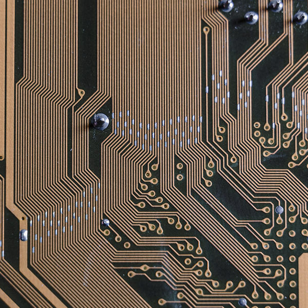
At its most fundamental level, a PCB trace is a continuous path of conductive material, typically copper, on a circuit board. Its primary function is to establish an electrical connection between two or more points. Think of it as a wire, but instead of being a separate component, it’s meticulously etched from a solid copper layer laminated onto a non-conductive substrate.
These traces form the complex network that allows electricity and data to flow, enabling every component—from the simplest resistor to the most complex processor—to communicate and function as part of a cohesive system. The dimensions of these traces, specifically their width and thickness, are not arbitrary. They are carefully calculated engineering parameters that determine the trace’s current-carrying capacity, signal integrity, and impedance, making their proper design and fabrication absolutely essential.
Why is Flawless Trace Design So Crucial for Your Device’s Performance?
A poorly designed or fabricated trace can be the source of countless frustrating and difficult-to-diagnose issues. The precision of these copper pathways directly impacts the functionality and reliability of the final electronic device. When trace fabrication is executed perfectly, it ensures the seamless operation of the entire system.
Firstly, it guarantees Signal Integrity. For high-speed digital circuits, the trace acts as a transmission line. Improper dimensions or fabrication defects can lead to signal degradation, reflections, and crosstalk, causing data errors or complete system failure. Secondly, it is vital for Power Integrity. Traces delivering power to components must be wide enough to handle the required current without overheating. An undersized trace can act like a fuse, leading to voltage drops or even melting, which can damage both the board and expensive components. Finally, meticulous fabrication contributes to the overall Reliability and Durability of the product, preventing issues like delamination or open circuits over the device’s lifespan, especially in harsh environments.
Which Key Factors Dictate Your PCB Trace Design?
Designing a PCB trace is a balancing act involving multiple electrical and physical constraints. Engineers must consider several variables to ensure the trace meets performance requirements without violating manufacturing limitations. At Tri-Win Circuits, our Design for Manufacturability (DFM) review process helps customers optimize these factors for reliable, high-yield production.
The core considerations for trace design are summarized below. Each factor influences the others, requiring a holistic approach to layout design. For example, a high-current requirement will necessitate a wider trace, which in turn impacts board density and routing possibilities.
| Design Factor | Why It’s Important | Key Considerations |
|---|---|---|
| Trace Width | Determines the maximum current the trace can safely carry (ampacity). | Current requirement, acceptable temperature rise, internal vs. external layer. |
| Trace Thickness | Along with width, this dictates the cross-sectional area and thus current capacity. | Standard copper weights (e.g., 1 oz, 2 oz), heat dissipation needs. |
| Trace Spacing | Prevents electrical arcing (short circuits) between adjacent traces. | Voltage difference between traces, board coating, environmental factors (humidity). |
| Controlled Impedance | Crucial for high-frequency signals to ensure clean signal transmission without reflections. | Trace width, substrate material (dielectric constant), distance to reference plane. |
| Trace Length & Routing | Affects signal timing and can introduce noise. | Matching lengths for differential pairs, avoiding right-angle bends, minimizing length for high-speed signals. |
How Does a Digital Design Become a Physical PCB Trace?
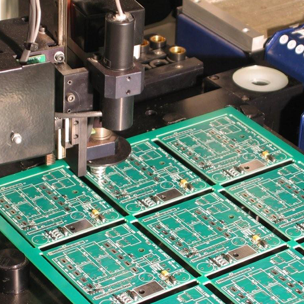
The transformation of a digital CAD design into a physical copper trace is a multi-step chemical and mechanical process. The most common method is subtractive manufacturing, where we start with a copper-clad laminate and remove the unwanted copper to leave only the desired trace pattern.
The process generally follows these key stages:
- Cleaning and Preparation: The base copper-clad laminate is thoroughly cleaned to remove any oils, debris, or oxidation, ensuring the subsequent layers will adhere properly.
- Photoresist Application: A light-sensitive film called a photoresist is applied over the entire copper surface.
- UV Exposure: Your digital design (the trace pattern) is printed onto a transparent film, or “phototool.” This is placed over the photoresist-coated board, which is then exposed to high-intensity UV light. The light hardens the photoresist in the areas that will become traces, while the unexposed areas remain soft.
- Developing: The board is washed in a developer solution, which removes the soft, unexposed photoresist, revealing the raw copper in the areas that need to be removed. The hardened photoresist protects the copper that will form the final traces.
- Etching: The board is placed in an etching bath, typically an acid solution, that dissolves the exposed copper. The hardened photoresist acts as a mask, protecting the desired trace pattern. This is a critical step where a manufacturer’s process control, like that at Tri-Win Circuits, is paramount to achieve precise trace widths and prevent over-etching (undercutting).
- Stripping: Once etching is complete, the remaining hardened photoresist is chemically stripped away, revealing the finished copper traces on the substrate.
What Are Common Flaws in Trace Fabrication and How Can They Be Prevented?
Even with a perfect design, manufacturing defects can compromise a trace’s integrity. Partnering with a quality-focused manufacturer that maintains tight process controls and conducts thorough inspections is the best defense against these issues. Our ISO 9001 and UL certifications at Tri-Win Circuits are a testament to our commitment to defect-free fabrication.
Some of the most common trace-related fabrication defects include:
- Undercutting: This occurs when the etchant solution seeps sideways underneath the photoresist, eating away at the sides of the trace. This results in a trace that is thinner than designed, increasing its resistance and reducing its current capacity. It is prevented by using advanced etching equipment and carefully monitoring chemical concentrations and exposure times.
- Over-etching (Opens): If the board is left in the etchant for too long, the solution can completely dissolve a thin trace, creating an “open circuit.” This is a catastrophic failure that renders the connection useless. Precise timing and automated process controls are key to prevention.
- Under-etching (Shorts): The opposite of an over-etch, this happens when not all of the unwanted copper is removed. The leftover copper slivers can form unintended connections, or “shorts,” between adjacent traces. This is avoided through proper board preparation and effective agitation in the etching bath.
- Scratches and Nicks: Physical damage from handling during the manufacturing process can reduce the cross-sectional area of a trace at a specific point, creating a “hot spot” that is prone to failure under load. A clean, well-organized facility and careful handling protocols are essential.
Beyond the Basics: What About Advanced Trace Configurations?
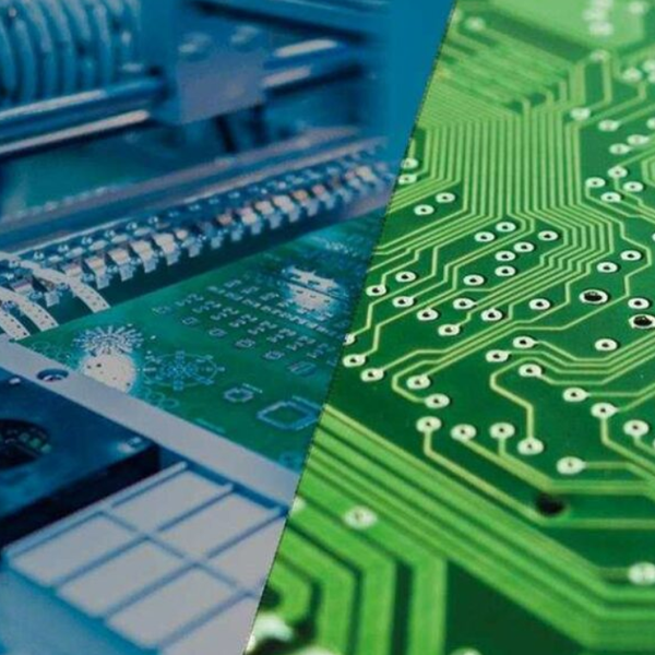
Modern electronics demand more than just simple point-to-point connections. As devices become smaller, faster, and more complex, advanced trace geometries are required. A capable manufacturing partner must have the technology to produce these intricate designs with high precision.
At Tri-Win Circuits, we specialize in advanced PCB technologies that rely on superior trace fabrication:
- HDI (High-Density Interconnect) Traces: HDI technology allows for much finer traces and spaces (we support down to 2.5/2.5 mil), enabling more components to be packed into a smaller area. This requires state-of-the-art imaging and etching processes to maintain integrity at such microscopic scales.
- Controlled Impedance Traces: Essential for high-frequency applications like RF, telecom, and high-speed data (USB, HDMI). We precisely control trace width, spacing, and the dielectric material to achieve a specific impedance (e.g., 50 ohms), ensuring clean signal transmission.
- Differential Pairs: These are two carefully matched traces that run parallel to each other. They are used to transmit high-speed signals by carrying the same signal in opposite phases, which helps cancel out electromagnetic interference (EMI). Fabricating them requires keeping their length and impedance perfectly matched throughout their entire path.
- Traces on Flexible and Rigid-Flex PCBs: Traces on flexible circuits must be designed to withstand bending and flexing without cracking or failing. This involves using specific routing techniques (e.g., curved corners, hatched ground planes) and materials, all of which demand specialized manufacturing expertise.
How Can Tri-Win Circuits Ensure Your Trace Fabrication is a Success?
Successfully fabricating a PCB trace is a collaborative effort between the designer and the manufacturer. While a robust design is the starting point, its ultimate realization depends entirely on the capabilities and quality standards of your fabrication partner. This is where Tri-Win Circuits excels.
We provide more than just manufacturing; we provide a partnership. Our experienced engineering team offers a comprehensive DFM check on every design, identifying potential issues with trace widths, spacing, or impedance characteristics before production begins. This proactive approach saves you time, reduces costs, and prevents board failures. Our advanced equipment, stringent quality control, and expertise in a wide range of PCB types—from standard Rigid FR-4 to complex, high-frequency Rigid-Flex boards—make us the ideal partner for your most demanding projects.
By choosing Tri-Win Circuits, you are ensuring that every trace on your board is fabricated with the utmost precision, delivering the performance and reliability your customers expect. Contact us today to discuss your next project and let us help you turn your design into a flawlessly executed reality.