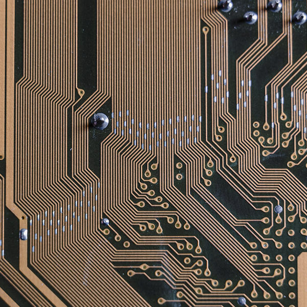
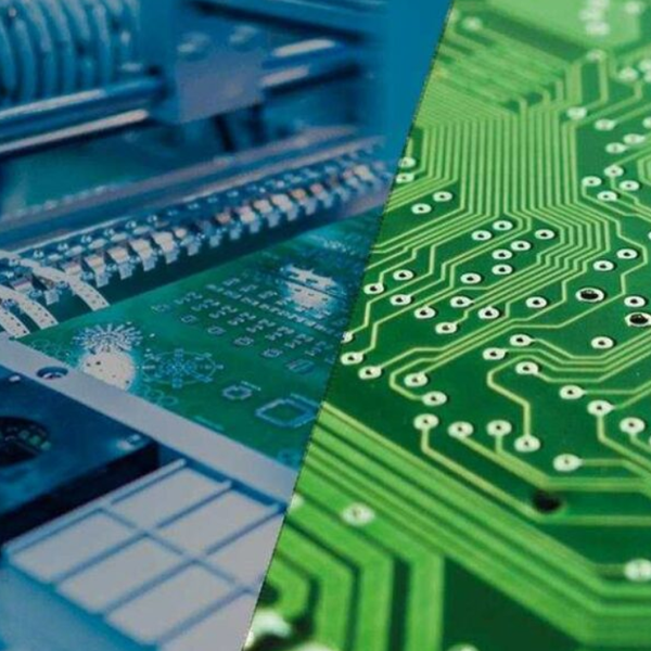
In modern electronics, the drive for miniaturization, cost reduction, and enhanced performance is relentless. One innovative technique gaining traction is the integration of passive components directly into the Printed Circuit Board (PCB) structure. At Tri-Win Circuits, with over two decades of experience in advanced PCB fabrication, we frequently assist our clients in implementing on-board components. Among these, the PCB trace inductor stands out as a clever solution for specific applications. Tri-Win will walk you through the entire process, from conceptual design to the critical manufacturing considerations needed to successfully fabricate an inductor on your PCB.

Why Should You Integrate Inductors into Your PCB Layout?
Before diving into the “how,” it’s essential to understand the “why.” Traditional surface-mount device (SMD) inductors are discrete components that must be picked, placed, and soldered onto a PCB. While effective, they have limitations. Fabricating an inductor directly using PCB traces, often called a planar or embedded inductor, offers a compelling set of advantages, particularly for high-frequency applications.
The primary benefits include:
- Cost and Assembly Reduction: By eliminating a discrete component, you reduce your Bill of Materials (BOM) cost. More importantly, you remove a step in the PCBA (PCB Assembly) process, which simplifies assembly, reduces potential points of failure, and can lower overall manufacturing costs.
- Miniaturization and Space Saving: Planar inductors utilize existing board space, freeing up valuable real estate on the PCB surface for other critical components. This is a significant advantage in dense, compact designs common in consumer electronics and mobile devices.
- Superior High-Frequency Performance: At high frequencies, PCB trace inductors can exhibit higher self-resonant frequencies (SRF) compared to many wire-wound SMD inductors. Their planar nature also results in highly repeatable performance with minimal parasitic variance between boards.
- Excellent Thermal Management: The large surface area of the copper traces allows for better heat dissipation compared to a tiny, concentrated SMD component, improving the thermal stability and reliability of the circuit.
However, it’s not a universal solution. PCB inductors are generally limited to lower inductance values (typically in the nanohenry (nH) range) and may have a lower Quality (Q) factor than their discrete counterparts. Therefore, they are best suited for applications like RF matching networks, filters, and high-frequency power converters where these characteristics are acceptable.
Which Planar Inductor Geometries Are Most Effective?
The shape, or geometry, of the copper trace directly defines the inductor’s performance. The goal is to maximize the magnetic field coupling within the trace structure. Several common geometries are used, each with its own trade-offs. The choice depends on the available space, required inductance, and desired Q factor.
At Tri-Win Circuits, we can precisely manufacture various complex shapes, but the most common and effective geometries are:
| Inductor Geometry | Description | Best For |
|---|---|---|
| Square Spiral | A trace that spirals inwards in a square shape. It’s the most common and straightforward geometry to design and model. | General-purpose applications; easy to lay out with standard CAD tools. |
| Circular Spiral | A trace that spirals inwards in a circular or near-circular (octagonal/hexagonal) shape. This geometry minimizes sharp corners. | Achieving a slightly higher Q factor, as it reduces current crowding at corners. |
| Meander Line | A simple back-and-forth “snake-like” pattern. It’s less space-efficient for a given inductance. | Low-inductance requirements or when layout constraints prevent a spiral. |
| Multi-Layer Inductor | A spiral that continues on multiple layers of the PCB, connected by vias. The magnetic fields of the layers add up. | Achieving higher inductance values in a smaller footprint than a single-layer spiral allows. |
What Key Design Parameters Govern PCB Inductor Performance?
Once you’ve chosen a geometry, several physical parameters must be carefully defined. These variables directly influence the final inductance, Q factor, and SRF. Precision in both design and manufacturing is critical here, as even small deviations can significantly alter electrical performance.
Key Design Variables:
- Trace Width (w): Wider traces result in lower series resistance, which generally increases the Q factor. However, this also increases parasitic capacitance to the ground plane, which can lower the SRF.
- Trace Spacing (s): The gap between adjacent turns of the spiral. Tighter spacing increases mutual inductance and thus the overall inductance value. However, it also increases inter-winding capacitance, which lowers the SRF. The minimum spacing is limited by the manufacturer’s capabilities.
- Number of Turns (n): More turns directly and significantly increase the inductance. This is often the primary variable adjusted to hit a target inductance value.
- Outer and Inner Dimensions: The overall footprint of the spiral (outer diameter) and the size of the central “hole” (inner diameter) affect the total inductance. A larger area generally yields higher inductance.
- Substrate Material and Thickness: The dielectric constant (Er) and thickness of the PCB substrate between the inductor layer and any ground planes will determine the parasitic capacitance. High-frequency materials from suppliers like Rogers or Teflon, which we regularly process at Tri-Win Circuits, offer stable and predictable dielectric properties.
How Can You Accurately Model and Calculate PCB Inductance?
Simply drawing a spiral is not enough; you must predict its performance. There are three main approaches to calculating and modeling your PCB inductor, ranging from simple approximations to highly accurate simulations.
1. Formula-Based Approximations: For simple spiral inductors, several empirical formulas exist. A modified version of the Wheeler formula is commonly used for single-layer planar inductors:
L ≈ (K₁ * µ₀ * n² * d_avg) / (1 + K₂ * ρ)
Where L is inductance, µ₀ is the permeability of free space, n is the number of turns, d_avg is the average diameter, and ρ is the fill factor. K₁ and K₂ are coefficients that depend on the geometry (square, hexagonal, etc.). While useful for initial estimates, these formulas don’t account for all parasitic effects.
2. Standalone Calculator Tools: Many free and commercial software tools are available specifically for calculating planar inductor values. You input the physical parameters (width, spacing, turns, etc.), and the tool provides an estimate of inductance, Q factor, and SRF. These are excellent for quick iterations during the design phase.
3. 2.5D/3D Field Solvers: For the highest accuracy, professional EDA (Electronic Design Automation) tools like Altium Designer, Cadence, or dedicated field solvers (like Ansys HFSS) are indispensable. These tools perform electromagnetic (EM) simulations on the exact layout, accounting for all parasitic effects, coupling to nearby traces, and the influence of the complete PCB stack-up. This is the most reliable method for verifying final performance before fabrication.
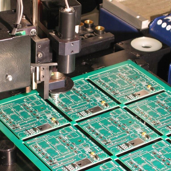
What Is the Manufacturing Process for Embedded Inductors?
From a manufacturing perspective, a PCB inductor is simply a precisely defined copper feature. The fabrication process is the same as for any other trace on a PCB, but the required precision is much higher. The success of your design relies entirely on your fabrication partner’s ability to consistently meet tight tolerances.
Here’s how it ties into the standard PCB manufacturing flow:
- Design Rule Check (DRC): When we receive your Gerber or ODB++ files at Tri-Win Circuits, our first step is a thorough Design for Manufacturability (DFM) check. For PCB inductors, we pay special attention to the specified trace width and spacing, ensuring they are within our advanced production capabilities.
- Imaging and Etching: The inductor pattern is transferred onto the copper-clad laminate using photolithography. The precision of this imaging step is paramount. The subsequent etching process removes the unwanted copper, and the control over the etchant and timing must be perfect to achieve the target trace width without over- or under-etching.
- Layer Lamination (for multi-layer inductors): If the inductor spans multiple layers, the individual cores are pressed together under immense pressure and heat. Precise layer-to-layer alignment is crucial to ensure vias connect the spiral segments correctly.
- Surface Finish and Solder Mask: A surface finish (like ENIG or OSP) is applied to protect the copper. The application of the solder mask must also be precise to avoid covering any part of the inductor that might be used as a contact point, while properly protecting the rest of the traces.
- Quality Control and Testing: Throughout the process, Automated Optical Inspection (AOI) verifies trace dimensions. After fabrication, electrical tests can be performed to confirm continuity. For critical applications, impedance or inductance can be verified using a network analyzer on a test coupon included on the production panel.
How Does Partnering with an Expert Fabricator Ensure Success?
As you can see, the gap between a well-designed PCB inductor and a functional one is bridged by manufacturing precision. A design that relies on 3-mil (0.076mm) trace/space is unmanufacturable for a standard-capability fab, but it is a routine process for a technologically advanced partner.
Partnering with an experienced manufacturer like Tri-Win Circuits provides critical advantages:
- Capability Alignment: We provide clear and detailed DFM guidelines, so you can design your inductor with full confidence that we can build it. Our investment in advanced imaging and etching technology allows for the tight tolerances that high-performance inductors demand.
- Material Expertise: Your choice of laminate affects performance. We have extensive experience with a wide range of materials, from standard FR-4 to specialized high-frequency substrates, and can advise on the best choice for your application and budget.
- Process Control: With certifications like ISO 9001, IATF 16949, and UL, our process control is rigorously managed. This ensures that every board in a production run has inductors with consistent, repeatable performance—a critical factor in RF and high-speed circuits.
- Collaborative Support: Our engineers are available to review your design before production, helping to identify potential manufacturing issues or suggest optimizations that could improve yield and performance.
Fabricating inductors on your PCB is a powerful technique for optimizing modern electronic designs. By understanding the interplay between geometry, design parameters, and the manufacturing process, you can successfully leverage this method to create smaller, more reliable, and cost-effective products. When you’re ready to turn your design into a reality, trust a partner with the technology and expertise to get it right. Trust Tri-Win Circuits.