Every revolutionary electronic device begins as an idea, but its physical heart is the Printed Circuit Board (PCB). This intricate network of copper traces and components is the foundation of modern technology. However, transforming a digital design file into a functional, reliable PCB is a complex manufacturing journey. Understanding this journey is crucial for engineers, designers, and innovators to optimize their designs for manufacturability, reduce costs, and ensure the final product’s success.
At Tri-Win Circuits, we don’t just manufacture PCBs; we bring your electronic innovations to life. With decades of experience as a one-stop solution for PCB fabrication and assembly, we’ve perfected every step of this process. Tri-Win offers an insider’s look into how professional-grade circuit boards are made, sharing the expertise that ensures every board we produce meets the highest standards of quality and performance.
Article Contents:
- 1. An Introduction to Professional PCB Fabrication
- 2. What Foundation is Your Circuit Board Built On?
- 3. How Are Multilayer PCBs Actually Constructed?
- 3.1 Creating the Inner Layers: The Circuit’s Core
- 3.2 What Holds It All Together? The Lamination Process
- 3.3 How Are Connections Made Between Layers? Drilling and Plating
- 3.4 Defining the Surface: The Outer Layer and Solder Mask
- 3.5 Which Surface Finish is Right for Your Project?
- 3.6 Adding the Final Touches: Silkscreen and Profiling
- 4. Why is Quality Assurance Non-Negotiable in PCB Manufacturing?
- 5. How Do You Choose the Right PCB Fabrication Partner?
- 6. Partner with Tri-Win Circuits for Flawless Fabrication
What Foundation is Your Circuit Board Built On?
Before any manufacturing can begin, two critical elements must be finalized: the board’s material and the design’s blueprint. These initial choices dictate the board’s performance characteristics, durability, and ultimately, its suitability for the intended application.
The Core Materials: Beyond Standard FR-4
The base material, or substrate, provides the rigid or flexible structure for the circuit. While FR-4 (a glass-reinforced epoxy laminate) is the industry workhorse due to its excellent balance of cost, durability, and thermal performance, many applications demand specialized materials. At Tri-Win Circuits, we handle a diverse range of substrates to meet any challenge, including high-frequency Rogers materials for RF applications, flexible Polyimide for Flex PCBs, and Aluminum-backed substrates for Metal Core PCBs (MCPCB) that require superior heat dissipation.
The Digital Blueprint: Gerber Files and DFM
Your design software outputs a set of files known as Gerber files. These files are the universal blueprint for PCB fabrication, detailing every layer of the board—from copper traces and drill holes to solder mask and silkscreen legends. Providing a complete and accurate set of files is the single most important step in the pre-production phase.
To prevent costly errors and production delays, we perform a thorough Design for Manufacturability (DFM) check on every design we receive. This crucial service involves analyzing your Gerber files to identify potential issues that could impact the fabrication process, such as trace widths that are too thin, insufficient clearance between elements, or missing drill files. This proactive approach is a core part of the Tri-Win advantage, ensuring your design is optimized for efficient, successful production from the very start.
| File Type | Description |
|---|---|
| Gerber Files (RS-274X) | Defines copper layers, solder mask layers, silkscreen layers, and paste layers. |
| NC Drill File (Excellon) | Specifies the location, size, and type (plated/non-plated) of all drill holes. |
| Board Outline | A file or layer indicating the precise physical dimensions and shape of the board. |
| Fabrication Drawing (Optional but Recommended) | A drawing that includes board stack-up details, special instructions, and tolerances. |
How Are Multilayer PCBs Actually Constructed?
Once the design is verified, the physical fabrication process begins. This is a multi-stage sequence where raw materials are transformed, layer by layer, into a finished circuit board. The process for a multilayer board is particularly intricate, requiring precision at every turn.
Creating the Inner Layers: The Circuit’s Core
For boards with more than two layers, the process starts with the inner layers. A sheet of laminate, which consists of the substrate core clad with copper foil on both sides, is used. This copper is coated with a light-sensitive material called photoresist. The Gerber file data for an inner layer is used to create a “phototool” or mask. This mask is placed over the resist-coated laminate, which is then exposed to UV light. The light hardens the photoresist in the areas that will become the circuit traces. The unhardened resist is washed away, and the exposed copper is etched off with a chemical solution, leaving only the desired copper circuitry behind.
What Holds It All Together? The Lamination Process
After the inner layers are etched and inspected, they must be bonded together to form the multilayer stack-up. The etched core layers are alternated with layers of “prepreg”—a fiberglass cloth pre-impregnated with epoxy resin. The entire stack, including copper foil for the outer layers, is then placed into a lamination press. Under immense pressure and high temperature, the resin in the prepreg melts, flows, and cures, bonding all the layers into a single, solid multilayer board. Precise alignment is critical here, which is why we utilize advanced optical alignment systems.
How Are Connections Made Between Layers? Drilling and Plating
To connect the different layers of the circuit, holes known as “vias” are drilled through the laminated board. We use high-speed, computer-controlled drills to create holes with extreme precision, sometimes just a few thousandths of an inch in diameter. For advanced High-Density Interconnect (HDI) boards, this may involve laser drilling for microvias.
After drilling, the board goes through a chemical deposition process to coat the inside of the holes with a very thin layer of copper. This is followed by a full electroplating process, where additional copper is plated onto the surface of the outer layers and down through the drilled holes. This creates the electrical connections—known as Plated-Through Holes (PTH)—that link the layers of the PCB together.
Defining the Surface: The Outer Layer and Solder Mask
Similar to the inner layer process, the outer copper layers are now imaged and etched to create the surface circuitry. Once this is complete, the board is covered with a solder mask. This is the green (or other color) layer you see on most PCBs. Its primary purpose is to protect the copper traces from oxidation and to prevent solder bridges from forming between closely spaced pads during the assembly process. A UV exposure process, using another phototool, defines where the mask should be removed to expose the pads where components will be soldered.
Which Surface Finish is Right for Your Project?
The exposed copper pads need a protective surface finish to ensure solderability and prevent oxidation. The choice of finish depends on the application, components used, and budget. As a full-service provider, Tri-Win Circuits offers all major surface finishes to meet your specific requirements.
| Finish Type | Advantages | Considerations |
|---|---|---|
| HASL (Hot Air Solder Leveling) | Low cost, excellent solderability, robust. | Uneven surface, not ideal for fine-pitch components. Lead-free options available. |
| ENIG (Electroless Nickel Immersion Gold) | Flat surface, good for fine-pitch and BGA, long shelf life. | Higher cost, more complex process. |
| Immersion Silver (ImAg) | Very flat surface, good for high-speed signals. | Can tarnish if handled improperly, shorter shelf life. |
| OSP (Organic Solderability Preservative) | Lead-free, flat surface, low cost. | Short shelf life, sensitive to handling. |
Adding the Final Touches: Silkscreen and Profiling
Next, the silkscreen layer is printed onto the board. This layer contains reference designators, component outlines, logos, and other helpful information for the assembly and testing stages. Finally, the individual boards are separated from the larger manufacturing panel. This is done either by V-scoring, which creates a V-shaped groove for easy snapping, or by routing, where a CNC machine cuts the board out along its precise outline.
Why is Quality Assurance Non-Negotiable in PCB Manufacturing?
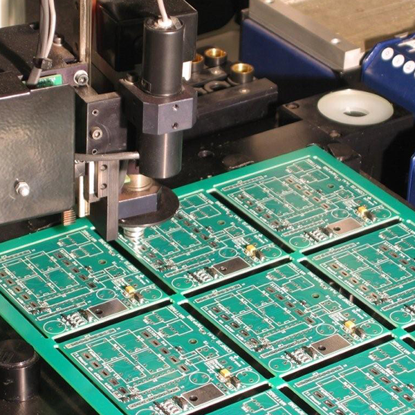
A beautifully fabricated board is useless if it doesn’t work. Rigorous quality control is woven into every step of our process. After fabrication, every board undergoes comprehensive testing to verify its integrity. This includes Automated Optical Inspection (AOI) to check for visual defects and an Electrical Test (E-Test), where every net on the board is checked for opens and shorts against the original design data. For complex multilayer or BGA boards, we utilize X-ray inspection to verify internal layer alignment and drill accuracy. Our commitment to quality is validated by our ISO 9001 and UL certifications, giving you peace of mind that your product is built to last.
How Do You Choose the Right PCB Fabrication Partner?
Choosing a manufacturer is as critical as the design itself. Look for a partner, not just a supplier. A true partner will have the technical capabilities to meet your project’s needs, whether it’s a simple 2-layer prototype or a complex rigid-flex assembly. They should hold key industry certifications as proof of their commitment to quality and offer robust engineering support, like the DFM checks we provide.
One of the most significant advantages is finding a partner who offers a one-stop solution. A company like Tri-Win Circuits, which manages everything from PCB fabrication to component sourcing and full turnkey assembly (PCBA), streamlines your entire supply chain. This integrated approach reduces lead times, minimizes communication errors between multiple vendors, and provides a single point of accountability for the quality of your final assembled product. It’s the most efficient path from concept to market.
Partner with Tri-Win Circuits for Flawless Fabrication
The PCB fabrication process is a sophisticated blend of chemistry, engineering, and precision manufacturing. By understanding its key stages, you can better prepare your designs for a smooth and successful production run.
At Tri-Win Circuits, we leverage our extensive expertise in fabricating Rigid, Flex, Rigid-Flex, and Metal Core PCBs to deliver unparalleled quality and reliability. From quick-turn prototypes to high-volume production, our state-of-the-art facility and dedicated team are ready to support your most demanding projects. Let us be your trusted partner in innovation. Contact us today to discuss your next project or to receive a quote for our end-to-end fabrication and assembly services.