In the world of high-speed digital electronics, success is measured in nanoseconds. Signal integrity is not just a goal; it is the bedrock upon which reliable performance is built.At the heart of signal integrity lies a critical concept: controlled impedance. As a leading PCB manufacturer with over two decades of experience, Tri-Win Circuits understands that the flawless execution of a controlled impedance design depends on clear, precise communication between the designer and the fabricator. Missteps here can lead to signal reflections, data errors, and costly board respins.

Tri-Win Circuits is designed to empower you, the designer, to create fabrication notes that leave no room for ambiguity. By mastering this crucial documentation, you ensure that your design intent is perfectly translated into a high-performance, reliable printed circuit board. Let’s bridge the gap between your schematic and a perfectly fabricated PCB.
Article Quick Links
- What Is The Fundamental Role of Controlled Impedance in Modern PCBs?
- Which Key Details Must Be Included in Your Impedance Fabrication Notes?
- How Should You Structure and Place Your Impedance Notes?
- Can You Provide Examples of Effective Impedance Callouts?
- What Common Pitfalls Should Be Avoided in Impedance Specifications?
- How Does a Manufacturer Like Tri-Win Circuits Use Your Notes?
What Is The Fundamental Role of Controlled Impedance in Modern PCBs?
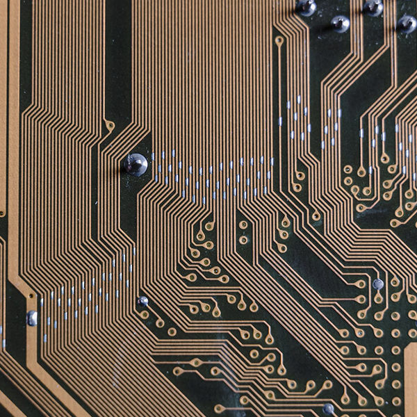
Before detailing what to write, it’s essential to understand why. Controlled impedance is the characteristic impedance of a transmission line formed by a PCB trace, its surrounding dielectric material, and its reference plane(s). For high-frequency signals (typically above 100MHz), the PCB trace no longer acts as a simple conductor but as a transmission line. Any inconsistency or change in impedance along this line can cause signal reflections and degradation.
Why is this a concern? These reflections can lead to a cascade of problems, including increased jitter, reduced noise margins, and ultimately, complete data corruption. For interfaces like DDR, USB, HDMI, Ethernet, and RF antennas, maintaining a constant impedance is non-negotiable. It ensures that the maximum signal power is transferred from the source to the load, preserving the integrity and clarity of the signal. In essence, controlling impedance is about managing the electromagnetic field behavior across your board, a foundational requirement for almost all modern electronics.
Which Key Details Must Be Included in Your Impedance Fabrication Notes?
Vague instructions lead to manufacturing uncertainties. To ensure we at Tri-Win Circuits can build your board to your exact specifications, your fabrication notes must be explicit and comprehensive. A well-defined impedance callout acts as a contract, defining the precise electrical performance you expect. Ambiguity forces the fabricator to make assumptions, which is a risk no high-speed design can afford.
The most effective way to communicate these requirements is through a clear table within your fabrication drawing. This format is universally understood and minimizes the chance of misinterpretation. Below is a detailed breakdown of the essential parameters to include for each controlled impedance trace or pair.
| Parameter | Description & Importance | Example |
|---|---|---|
| Trace Type | Specify if the trace is Single-Ended (one signal trace over a reference plane) or Differential Pair (two coupled traces). This is the most fundamental classification. | Differential Pair |
| Target Impedance (Zo / Zdiff) | The desired impedance value in Ohms (Ω). For differential pairs, this is the differential impedance (Zdiff). For single-ended, it’s the characteristic impedance (Zo). | 100 Ω |
| Tolerance | The acceptable deviation from the target impedance, typically expressed as a percentage. Standard tolerance is ±10%, while high-precision applications may require ±7% or even ±5%. | ±10% |
| Applicable Layers | Clearly state which layer(s) of the PCB contain these controlled impedance traces. Use layer names that match your Gerbers (e.g., L1, L3, Top, Inner 1). | L2, L5 |
| Reference Layers | Specify the adjacent copper plane(s) that the trace uses as its reference for impedance calculation (e.g., L1 referencing L2 GND). This is critical for microstrip and stripline configurations. | Ref: L1, L3 |
| Trace Width / Spacing | Provide your calculated trace width for single-ended traces or the trace width and the gap (spacing) between traces for differential pairs. While the fabricator will adjust this based on the final stack-up, providing your design value is crucial as a starting point and for DFM checks. | Width: 4 mil / Gap: 5 mil |
| Associated Nets | Listing the net names (e.g., USB_D+, USB_D-, TX_CLK) is not always mandatory but is extremely helpful for cross-referencing and verification. | USB_D+, USB_D- |
How Should You Structure and Place Your Impedance Notes?
With the necessary information compiled, the next question is where to place it for maximum clarity and visibility. Consistency is key. Your fabrication partner shouldn’t have to hunt for critical data across multiple files. The industry-standard and most recommended practice is to centralize this information in one primary location: the fabrication drawing.
Your fabrication drawing is the master blueprint for PCB construction. Placing an impedance control table here ensures it is seen and formally acknowledged as part of the manufacturing specification. Additionally, you should:
- Create a Dedicated “Impedance Control” Section: Use a clear heading on your fabrication drawing to house the impedance table. This makes it impossible to miss.
- Visually Call Out Traces on the Layer Itself: While not a replacement for the fab drawing notes, it’s good practice to add text or symbols on a mechanical or Gerber layer to highlight the physical locations of controlled impedance traces on the board layout. This provides a helpful visual reference.
- Reference the Stack-up Drawing: Your impedance notes are intrinsically linked to the PCB stack-up. Ensure your fabrication drawing either includes the full stack-up details or clearly references a separate, detailed stack-up drawing. The dielectric material (e.g., FR-4, Rogers), its dielectric constant (Dk), and layer thicknesses are vital for the fabricator to achieve the target impedance.
Can You Provide Examples of Effective Impedance Callouts?
Let’s translate theory into practice. Here are two examples of clear, concise fabrication notes as they would appear in a fabrication drawing.
Example 1: Single-Ended USB Full Speed Data Line
Note Title: CONTROLLED IMPEDANCE REQUIREMENTS
Note Content: “ALL TRACES IDENTIFIED IN THE TABLE BELOW MUST MEET THE SPECIFIED IMPEDANCE. FABRICATOR TO ADJUST TRACE WIDTHS AND DIELECTRIC SPACING AS NEEDED TO ACHIEVE TARGET IMPEDANCE AND PROVIDE A FINAL STACK-UP. IMPEDANCE TEST COUPONS ARE REQUIRED FOR VERIFICATION.”
- Type: Single-Ended
- Impedance: 90 Ω ± 10%
- Nets: USB_D+
- Layer: L1 (Top)
- Reference Plane: L2 (GND)
- Design Width: 5.5 mil
Example 2: Differential Pair for PCIe
(Within the same table as the above example)
- Type: Differential Pair
- Impedance: 85 Ω ± 10%
- Nets: PCIE_TX_P, PCIE_TX_N
- Layer: L3 (Inner)
- Reference Planes: L2 (GND), L4 (PWR)
- Design Width/Gap: 4 mil / 6 mil
What Common Pitfalls Should Be Avoided in Impedance Specifications?
Even with the best intentions, errors in fabrication notes can occur. Being aware of these common mistakes can save you significant time and money.
- Omitting the Tolerance: Simply stating “100 Ω differential” is incomplete. Without a tolerance (e.g., ±10%), the fabricator doesn’t know the acceptable range, which affects process control and testing.
- Forgetting Reference Planes: A trace’s impedance is defined relative to its reference plane(s). Failing to specify which layer(s) serve as the reference for a given trace is a critical omission.
- Contradictory Information: Ensure the notes on your fabrication drawing, the details in your stack-up, and any notes in the Gerber files are consistent. Conflicting information forces the fabricator to stop production and ask for clarification, causing delays.
- Specifying Unrealistic Tolerances: While tight tolerances like ±5% are achievable, they require premium materials and more rigorous process control, which increases cost. Only specify tighter-than-standard tolerances if your design genuinely requires it. Always discuss these needs with your fabrication partner beforehand.
How Does a Manufacturer Like Tri-Win Circuits Use Your Notes?
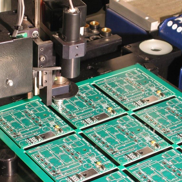
When you submit a design with clear impedance notes to an experienced fabricator like Tri-Win Circuits, a systematic process begins. This is where your careful documentation pays off.
- DFM (Design for Manufacturability) Review: Our engineers first review your notes and stack-up. We use advanced modeling software to verify if your specified trace widths and materials will achieve the target impedance. If we foresee any issues, we proactively contact you with suggestions for adjustments.
- Stack-up Finalization: Based on our available material inventory and process capabilities, we finalize the precise layer stack-up, adjusting trace widths and dielectric thicknesses to hit the center of your impedance target. This finalized stack-up is sent to you for approval before production.
- Process Control: During fabrication, we meticulously control the etching processes to achieve the precise trace geometries and the lamination process to ensure consistent dielectric thickness.
- Verification with TDR Testing: This is the ultimate proof of success. We fabricate impedance test coupons on the same panel as your boards. These coupons replicate your trace configurations. After fabrication, we use a Time Domain Reflectometer (TDR) to send a signal through the coupon and measure the actual impedance, generating a report to verify that the results are within your specified tolerance.
Ultimately, your controlled impedance PCB fabrication notes are the most critical tool for communicating your high-speed design requirements. By creating notes that are clear, complete, and correct, you enable a smooth manufacturing process and ensure the final product performs exactly as you designed it.
Partnering with a knowledgeable manufacturer who values this communication is the final piece of the puzzle. At Tri-Win Circuits, we pride ourselves on this partnership, turning your precise specifications into reliable, high-performance circuit boards.