Are you tired of rigid electronics that limit design? Does connecting components in tight spaces feel impossible? Standard circuit boards just don’t bend or fit easily. I faced this issue too when working on a small gadget project.
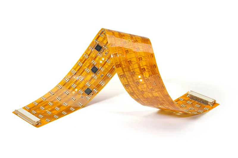
A flexible PCB is a circuit board made on a bendable plastic substrate, like polyimide. It allows circuits to bend and flex, fitting into shapes and spaces where rigid boards cannot go. This technology opens up many new possibilities in electronic design.
Table of Contents:
- How Do You Make a Flexible PCB?
- How Do You Design a Flexible PCB?
- What Are the Different Types of Flexible PCBs?
- How Sharp Can a Flexible PCB Be Bent?
- Where Are Flexible PCBs Used?
- What Are the Advantages of Flexible PCBs?
- What Are the Limitations of a Flexible PCB?
- How Many Layers Can a Flexible PCB Have?
How Do You Make a Flexible PCB?
Making a flexible PCB seems complex, but it follows clear steps. Understanding this helps you see why they are special. Let’s look at how it is done.
Making a flexible PCB involves printing circuit patterns onto a thin, flexible base material, usually polyimide. Layers are built up with adhesive, conductors, and protective coatings through steps like etching, plating, and lamination.
Key Production Steps
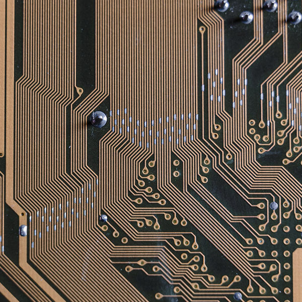
Making a flexible PCB involves many precise steps. First, you start with the flexible core material. This is often polyimide because it handles heat and bending well. Copper foil is then attached to this core. This is where the circuit will go.
Next, the circuit pattern is put onto the copper. This can be done using photolithography. A photoresist material is applied, exposed through a mask showing the circuit design, and then developed. The unexposed photoresist is washed away.
This leaves the circuit pattern protected. Then, the unwanted copper is etched away using chemicals. The remaining copper forms the traces.
Adding Protection and Support
After etching, protective coatings are added. This is often a coverlay, which is another flexible layer with openings for connecting components. Soldermask is also used. These layers protect the circuits from damage and the environment.
Sometimes, stiffeners are added to parts of the flexible board. These stiffeners are often made of FR4 or polyimide. They give support to areas where components are soldered or where connectors attach. This makes these areas more robust.
Finishing Processes
Holes for components or vias are drilled or punched. Plating processes add copper to the holes and surface features. Finally, the boards are cut to their final shape. This can be done by punching or using a laser.
Here is a simple overview:
| Step | Action | Purpose |
| 1 | Prepare Base Material | Get the flexible core ready. |
| 2 | Apply Copper | Add conductive layer. |
| 3 | Pattern Circuit | Transfer design to copper. |
| 4 | Etch Copper | Remove unwanted copper. |
| 5 | Drill Holes | Create vias and component pads. |
| 6 | Plate | Strengthen traces and holes. |
| 7 | Add Coverlay/Mask | Protect the circuits. |
| 8 | Add Stiffener (Optional) | Add rigid support to certain areas. |
| 9 | Cut | Shape the final board. |
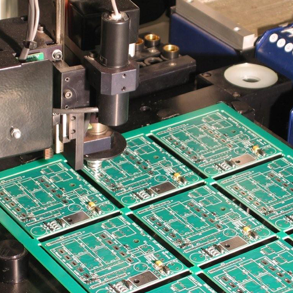
Quality Control in Manufacturing
You need careful process control at every stage. This ensures the board can bend correctly and reliably. Testing is also done throughout the process to check for errors or defects. For example, electrical tests verify that the circuits are connected right and have the correct resistance. Peel tests check the strength of the bond between layers.
How Do You Design a Flexible PCB?
Designing a flexible PCB is different from designing a rigid one. You must think about how it will bend and move. This adds new rules to the design process.
Designing a flexible PCB requires considering material properties and how the board will bend. You need to route traces carefully to avoid stress points, use larger bend radii, and plan for areas that need stiffening or component placement.
Key Design Considerations
When I design a flexible PCB, I always start by thinking about its final shape and how it will bend. This is the most important part. You cannot just route traces like on a flat board.
You must avoid sharp corners on traces. Sharp corners create stress points when the board bends. Traces should run perpendicular to the bend line if possible. If they must cross a bend line, use curves or angle them slightly.
Pads and vias also need special attention. They should not be placed on the bend line itself. Place them away from areas that will flex often. Adding tear-dropping to pads helps strengthen the connection to the trace. This makes it less likely to break with repeated bending.
Material and Stiffener Choices
Material choice is also part of the design. Polyimide thickness and copper weight affect flexibility and strength. Adhesives also play a role. You need to know the properties of the materials you plan to use.
Connectors and heavy components need support. You usually add stiffeners in these areas. This gives a rigid base for soldering and plugging in connectors.
Here are some design points to keep in mind:
- Avoid putting vias or components on bend lines.
- Route traces with curves, not sharp 90-degree angles.
- Make bend radii as large as the application allows.
- Consider copper weight and layer count for flexibility.
- Add stiffeners for components and connectors.
- Use tear-dropping on pads for strength.
Real-World Design Examples
For example, in a camera module for a smartphone, the flex PCB connects the camera sensor to the main board. This flex cable needs to fit into a very tight space and often bends around corners. The design must ensure the traces don’t break with repeated opening and closing of the phone or during assembly.
Another example is a wearable fitness tracker. The flex PCB conforms to the shape of the wristband. The design must handle constant flexing as the person moves.
Testing Your Flex Design
Testing the design is crucial. You can use simulation software to model how the board will bend and where stress points might occur. After getting prototypes, you need to perform bending tests. This involves bending the board repeatedly to see if it fails and where. You also check for electrical continuity during and after bending.
What Are the Different Types of Flexible PCBs?
Flexible PCBs come in different forms. Each type is suited for different needs and levels of complexity. Knowing the types helps you choose the right one.
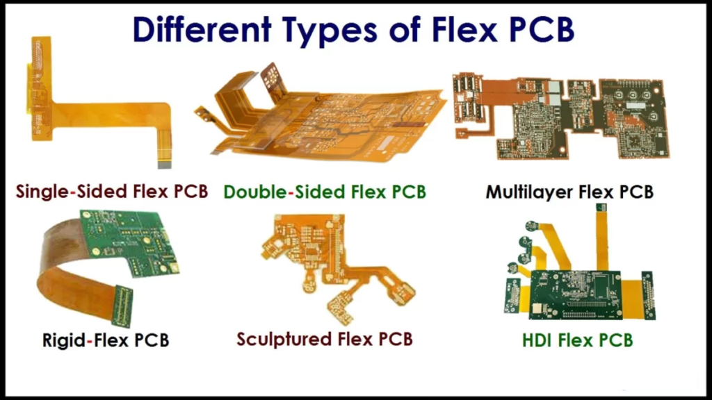
Flexible PCBs include single-sided, double-sided, and multilayer types. They also include rigid-flex boards, which combine flexible and rigid sections, and HDI (High-Density Interconnect) flex boards for complex, miniaturized designs.
Single and Double-Sided Flex
There are a few main types of flexible PCBs. The simplest is single-sided flex. It has one layer of copper on a flexible base. This is good for simple connections or when cost is important. It bends easily in one direction.
Double-sided flex has copper layers on both sides of the flexible base. Vias connect the two layers. This allows for more complex routing and higher circuit density. It can still bend, but maybe not as tightly as single-sided.
Multilayer and Rigid-Flex
Multilayer flex boards have three or more layers of copper. These layers are laminated together with flexible dielectric materials and connected by vias. Multilayer flex is used for very complex circuits that need high density. Bending ability decreases as the number of layers increases.
A very useful type is rigid-flex. This board has both rigid and flexible areas. The rigid parts are often made of FR4, like a standard PCB. The flexible sections connect the rigid parts. This is great because you can mount components on the rigid parts for stability and use the flex parts for connections in tight spaces. An example is in cameras, where rigid sections hold the lens and sensor, and a flex section connects to the main board.
HDI Flex for Miniaturization
HDI flex is another type. HDI stands for High-Density Interconnect. These boards have very fine lines, small vias, and high connection density. They are used in very small electronics, like smartphones and medical implants, where space is limited. Combining HDI technology with flex allows for highly miniaturized and bendable circuits.
Here is a comparison of some types:
| Type | Copper Layers | Flexibility | Complexity |
| Single-sided | 1 | High | Low |
| Double-sided | 2 | Medium | Medium |
| Multilayer | 3+ | Lower | High |
| Rigid-Flex | Mixed | Mixed | High |
| HDI Flex | Mixed | Can be High | Very High |
Choosing the Right Type and Testing
Choosing the right type depends on the application’s needs for bending, space, and circuit complexity. For instance, a simple cable replacement might use single-sided flex. A complex medical device might need rigid-flex or multilayer HDI flex.
Testing different types involves checking their bend radius limits and how well they perform electrically after bending. You also need to check how they stand up to environmental factors like temperature changes and humidity, especially in critical applications like medical or automotive.
How Sharp Can a Flexible PCB Be Bent?
Flexible PCBs are bendable, but not infinitely bendable. There are limits to how sharply they can bend. Knowing this limit is key for good design.
The minimum bend radius for a flexible PCB depends on its construction, like the number of layers and material thickness. Single-layer flex can bend very tightly, sometimes down to 1mm radius or less, while multilayer or rigid-flex boards require larger radii.

Understanding Bend Radius Limits
The bend radius is the smallest radius a flex circuit can bend around without damage. If you bend a flex circuit too sharply, you can stress the copper traces or the substrate material. This can cause the traces to crack or break, leading to circuit failure.
Many factors affect the minimum bend radius. The number of copper layers is a big one. A single-layer flex board can bend much tighter than a 4-layer or 8-layer board. Each extra layer adds stiffness. The thickness of the base material and the copper also matters. Thinner materials allow for tighter bends.
The type of copper used can also affect bending. Rolled annealed copper is often used in dynamic flexing applications because it is more flexible than electrodeposited copper. How the traces are routed also plays a role. Traces running perpendicular to the bend line can tolerate tighter bends than traces running parallel to it.
Here are typical minimum bend radii guidelines:
| Flex PCB Type | Recommended Minimum Bend Radius |
| Single-sided | 6x total thickness (dynamic); 1x total thickness (static) |
| Double-sided | 10x total thickness (dynamic); 5x total thickness (static) |
| Multilayer (3+ layers) | 15x total thickness (dynamic); 10x total thickness (static) |
Note: Static bending is when the board is bent once for installation. Dynamic bending is when the board bends repeatedly during use. Dynamic applications require larger bend radii for reliability.
Examples of Bend Radius in Use
For example, a flex cable in a printer head moves back and forth many times. This is a dynamic application. The design must use a large bend radius and durable materials to prevent failure over millions of cycles.
In contrast, a flex board connecting buttons on a remote control might only bend slightly during assembly. This is mostly a static bend, allowing a smaller radius.
Testing for Bend Reliability
To test the bending limits, engineers perform cycling tests. They put the flex circuit in a machine that bends it back and forth a set number of times. They check for electrical faults during or after the test. This helps determine the reliable bend radius for the specific design and materials. Using a microscope to inspect traces after bending also shows if there is any damage.
Where Are Flexible PCBs Used?
Flexible PCBs are everywhere, even if you don’t see them. Their unique ability to bend and fit makes them useful in many products. They solve tough connection problems.
Flexible PCBs are used in many applications where space is limited or bending is required. Common uses include smartphones, cameras, laptops, medical devices, automotive electronics, wearables, and industrial equipment for connections and sensor integration.

Consumer Electronics
I see flexible PCBs in many devices I use every day. One common place is inside my smartphone. Flex circuits connect the camera module, the display, the battery, and buttons to the main logic board. They fit into the phone’s slim shape better than rigid boards could.
Think about a modern laptop. Flex circuits are used for connecting the keyboard, trackpad, and display to the motherboard. They allow the lid to open and close many times without breaking the connections.
Automotive Applications
Another big area is automotive. Modern cars have many electronic systems. Flexible circuits are used in dashboards, lighting systems, and sensor arrays. They can route complex wiring in tight spaces and reduce the weight compared to traditional wire harnesses. This is important for fuel efficiency.
Medical and Industrial Uses
Medical devices also rely heavily on flex PCBs. They are used in things like hearing aids, pacemakers, and endoscopes. Their small size, flexibility, and reliability are critical for these life-saving or diagnostic tools. For example, in an endoscope, a tiny flex circuit connects the camera and light at the tip to the control unit.
In industrial robotics, flex circuits can move with the robotic arm, providing connections to sensors and motors without bulky wiring.
Here are some places where flex PCBs are commonly found:
- Consumer Electronics (Phones, Cameras, Laptops, Tablets)
- Automotive (Dashboard, Lighting, Sensors, Infotainment)
- Medical Devices (Implants, Diagnostic Tools, Monitoring Equipment)
- Wearables (Smartwatches, Fitness Trackers)
- Industrial Equipment (Robotics, Sensors, Controls)
- Aerospace and Defense (Avionics, Satellites)
- LED Lighting (Connecting LEDs in curved or tight spaces)
Testing for Specific Applications
When choosing a flex PCB for an application, you need to test its performance under the specific conditions it will face. For automotive use, tests include vibration, temperature cycling, and humidity exposure. For medical implants, biocompatibility and long-term reliability testing are essential. You also need to test repeated bending if the application involves movement.
What Are the Advantages of Flexible PCBs?
Flexible PCBs offer several key benefits compared to rigid boards. These advantages make them the preferred choice for many modern electronic designs. Let’s explore why they are so useful.
Flexible PCBs offer significant advantages including space savings due to their ability to bend, reduced weight compared to traditional wiring, improved reliability through fewer connections, and simplified assembly processes by integrating multiple boards and connectors.
Space Saving and Weight Reduction
One major advantage is space saving. Flexible circuits can bend and fold, allowing them to fit into irregular or very small spaces. This is impossible with rigid PCBs. In crowded electronic devices, this ability is critical for miniaturization. They also reduce the need for bulky wires and connectors.
Weight reduction is another big plus. Flexible PCBs are much lighter than traditional wiring harnesses made of many individual wires and connectors. This is very important in applications like aerospace, automotive, and portable electronics where every gram matters. For example, replacing a wire harness with a flex circuit in a car can save noticeable weight.
Increased Reliability
Reliability is often improved. A flex circuit integrates multiple connections and even entire circuit boards into a single, continuous structure. This means fewer solder joints and connector points. Each connection point is a potential point of failure. By reducing these, the overall reliability goes up. This is a key reason they are used in critical applications like medical implants and military equipment.
Simplified Assembly
Assembly is also simpler and cheaper. Instead of connecting many wires to multiple connectors on several rigid boards, a single flex circuit can replace them. This reduces manual labor and the chance of wiring errors during production. For example, in a laptop hinge, one flex cable connects the display to the base, replacing many individual wires.
Here are some main advantages:
| Advantage | Explanation | Benefit |
| Space Saving | Can bend/fold into tight spaces. | Enables miniaturization. |
| Weight Reduction | Lighter than wire harnesses. | Improves portability, efficiency. |
| Increased Reliability | Fewer connection points. | Reduces failure risk. |
| Simplified Assembly | Single part replaces multiple. | Lowers manufacturing cost. |
| Improved Heat Dissipation (Metal-backed flex) | Can use metal layers for heat spreading. | Better thermal management. |
Verifying the Benefits
You need to test that the chosen flex design provides these benefits in your specific product. For space saving, check the overall product size reduction. For weight, weigh the flex assembly versus the traditional method. For reliability, conduct stress tests like vibration and thermal cycling, alongside bend cycle testing if applicable. Comparing failure rates between flex and rigid assemblies is a good way to measure reliability improvement.
What Are the Limitations of a Flexible PCB?
While flexible PCBs offer great benefits, they also have some downsides. It’s important to know these limitations. This helps you decide if flex is the right choice for your project.
Flexible PCBs have limitations including higher manufacturing costs compared to rigid boards, greater difficulty in repair or modification, potential damage from sharp bending if design rules are not followed, and limitations on component size and weight in flexible areas.
Cost and Repair Challenges
One main limitation of flexible PCBs is the cost. They are generally more expensive to design and manufacture than standard rigid PCBs. The specialized materials and processes required for flexible circuits add to the cost. This can be a barrier for cost-sensitive applications, especially in low volumes.
Repairing or modifying a flexible PCB is also harder. The materials are thin, and the traces are often narrow. Reworking components on the flexible base is difficult and can easily damage the circuit. If a part of the flex circuit is damaged, often the whole board needs to be replaced. This makes troubleshooting and repair during prototyping or in the field more challenging.
Durability Concerns
They are also less durable than rigid boards in some ways. While they can bend, they are susceptible to damage from sharp objects or abrasion. If they are bent too sharply or stressed incorrectly, the traces can break internally. This requires careful handling during assembly and use. You cannot treat them like a standard, tough rigid board.
Component and Thickness Limits
Placing heavy or large components directly on the flexible part of the board is difficult. The flexible material cannot support much weight or stress from large components or connectors. You usually need to add stiffeners or place these components on rigid sections in rigid-flex designs. For instance, a large connector or a heavy processor chip cannot go directly on a flexing area.
The thickness of multilayer flex boards can become a limitation. As you add more layers for complex circuits, the overall thickness increases. This reduces the flexibility and increases the minimum bend radius. For very high layer counts, the board might not be very flexible at all.
Here are some common limitations:
- Higher initial cost.
- Difficult to repair or modify.
- Susceptible to damage from sharp bends or physical stress if not designed or handled properly.
- Limited component weight and size on flexible areas without stiffeners.
- Stack-up complexity and thickness increase with more layers.
- Thermal management can be tricky on thin substrates without specific features.
Evaluating Limitations for Your Project
When evaluating if these limitations affect your design, you should consider the total product cost, not just the PCB cost. Sometimes the assembly savings or space reduction from using flex makes the higher board cost acceptable. For durability, test the board under realistic stress conditions, including handling during assembly and expected flexing in the final product. Compare the failure points and modes to a potential rigid board or wiring solution.
How Many Layers Can a Flexible PCB Have?
The number of layers in a flexible PCB affects its complexity and flexibility. You might wonder how many layers are possible. The answer depends on what you need the board to do.
Flexible PCBs can range from single-layer designs up to multilayer structures with many layers. While single and double-sided are common, complex designs can have 10 layers or more, especially in rigid-flex constructions, though increasing layers reduces flexibility.
Single and Double-Sided Layers
Flexible PCBs can be made with different numbers of copper layers. The simplest is a single-layer board. It has one copper layer on a flexible substrate. This is the most flexible type. It is used for simple interconnections.
Double-sided flex boards have two copper layers, one on each side of the flexible core. Vias connect traces between the two layers. This allows for more complex routing than single-sided boards. They are less flexible than single-sided but still very useful.
Multilayer Flex and Rigid-Flex
Multilayer flexible PCBs have three or more copper layers. These layers are laminated together with flexible dielectric materials between them. Vias connect the layers. As the number of layers increases, the board gets thicker and less flexible. High layer counts are used for very dense and complex circuits that cannot fit on fewer layers.
In rigid-flex boards, the flexible sections can also have multiple layers. However, the number of layers in the flexible part is often kept lower than in the rigid parts to maintain some flexibility. Common flexible layer counts in rigid-flex might be 1, 2, 4, or 6 layers. Designs with 10 or more layers in the flex section are possible but are very stiff and have limited bending capability.
Here is a general idea:
| Layer Count | Complexity Level | Typical Flexibility |
| 1-2 | Low to Medium | High to Medium |
| 3-6 | Medium to High | Medium to Lower |
| 7+ | High to Very High | Lower |
| Rigid-Flex (Flex part) | Varies (often 1-6 layers in flex area) | Varies depending on layer count |
Balancing Layers and Flexibility
The choice of layer count depends on the circuit density required and the flexibility needed. If you need high density and don’t need much bending, more layers are possible. If you need tight bends, fewer layers are better. For example, a simple sensor connection might use a 1-layer flex. A complex circuit board needing to fit into a curved product might use a 4-layer or 6-layer flex.
When deciding on the layer count, you need to balance electrical needs with mechanical needs. Routing all signals might require many layers, but this impacts how much the board can bend. Simulation tools can help analyze signal integrity with higher layer counts. Testing involves checking the bend radius limits for the chosen layer count and ensuring the board still performs electrically after bending, especially at high speeds if applicable.
Conclusion
Flexible PCBs are important in modern electronics. They let us design products that are smaller, lighter, and can fit into complex shapes. They offer many benefits like saving space and improving reliability compared to old ways of connecting parts. But they also have challenges, like higher cost and being harder to fix. The way they are made and designed is key to making them work right, especially when we think about how much they need to bend and how many layers they have. Understanding the different types and their limits helps engineers pick the best solution for new and innovative products.